In the previous blog in this series, we described the importance of interface level measurement in the oil and gas industry, and then defined the various types of interfaces. In this post, we examine two of the four most prominent methods for measuring liquid and interface level in oil and gas applications: guided wave radar and capacitance.
Guided Wave Radar
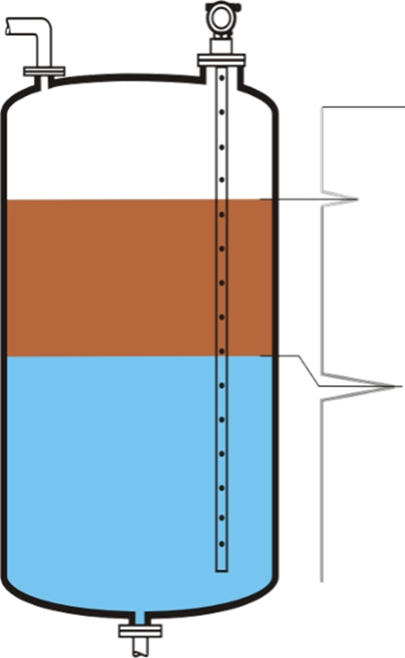
Guided wave radar (GWR) level measurement works by generating high-frequency microwaves, then coupling these to and guiding them along a metal probe into the liquid to be measured. These waves are reflected due to a change in impedance upon contacting the surface. The time required to travel to the surface and back is evaluated by the transmitter’s electronics and translated into a level value.
These instruments are useful for quantifying total and interface level in clear separation applications where the layers exhibit distinctly different dielectric constants. As the high frequency pulses meet the top layer, a limited portion of the signal is reflected and as the remaining pulses reach the second surface, they are also reflected back to the receiver. The timing of the signal receipt informs the distance of both surface layers from the probe and this data is then converted to separate overall and interface level values.
The upper layer must have a dielectric constant < 10 and be well defined to account for reduction of the microwave pulse speed as it passes through.
The difference in dielectric constant of the upper and lower layers must be > 10 to achieve a reliable interface level.
GWR technology is best used in applications with clear interfaces or with emulsion layers < 2″ in depth. Emulsion layers greater than 2” prevent the microwave pulses from producing two strong distinct reflections. Additionally, the dielectric constant of the top layer must be known to ensure GWR can work effectively.
Capacitance
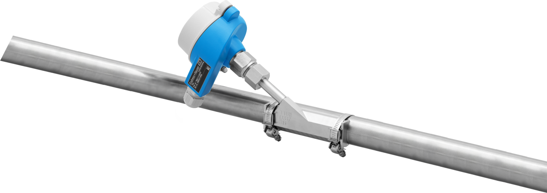
The second technology frequently used for oil and gas interface level measurement is capacitance. This principle can be deployed in metallic vessels, with the surrounding conductive tank walls and level instrument probe acting as a capacitor in continuous level measurement applications. The media in the tank and probe insulation constitute the dielectric, and capacitance varies based on the amount of conductive liquid present in the tank.
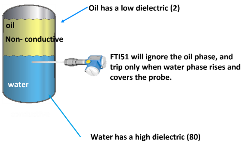
Nonconductive mediums with a low dielectric constant cause miniscule capacitance change, while conductive liquids with a high dielectric constant produce large and measurable variances. In many oil and gas interface applications, the medium with the lower dielectric constant is on top, e.g., hydrocarbon on water. The upper medium provides a minimal contribution to the overall capacitance value, so only the water level has a noticeable effect on the capacitance measured. For this effect to work properly, the dielectric constant of the two mediums must be substantially different.
In addition to continuous measurement, this principle is useful when used in point measurement switches to detect and classify various types of process media. For example, the FTI51 capacitive level switch can be used to detect conductive liquids in a vessel, ignoring oil, but triggering an alarm when water reaches a certain point.
Capacitance level measurement is effective for measuring interface level, even in the presence of emulsion layers, with one of the fastest response times among all level technologies. Sensitivity can be impacted in the event of nonconductive build up requiring adjustment or maintenance over time. Additionally, a horizontally mounted capacitance switch cannot be used to measure the total level within a vessel of mixed media.
Your decision on which technology is correct for your application will depend upon your measurement needs. If both overall and interface level is required in applications with little to no emulsion layer, Guided Wave Radar is the “clear” solution. If your application has a significant emulsion layer and the overall level is not critical, a capacitance probe is a highly effective solution.
In the third and final blog in this series, we’ll explore multiparameter and radiometric measurement technologies for quantifying and classifying trickier interface profiles.
For further questions regarding topics discussed in this blog, please fill the form out below to speak to one of our experts: